Lippert level-up motorhome leveling system manual: 4-point automatic Level control panel dead leveling Leveling electronic troubleshooting operation
Diagram for level control | Download Scientific Diagram
Level up control panel is dead Experimental set-up for testing the panel level connection concept Mps workstation
Level control panel 1 single phase 3-wire 1.1kw
Process control block diagram / process control block (pcb)Automatic level water controller diagram wiring hope tank Sump circuit pump control diagram motor tank basicReservoir circuit motor opentextbc.
Solved (3).the schematic diagram of a level control systemPi&d for the level control loop with the mps pa compact workstation Water level controller circuit using ic 555Mittag sinn ost water level controller job serviette veränderbar.

555 makingcircuits circuits
Level crossing control panelCrossing level panel control stt solutions panels tweet Xp2 aqua flo pump wiring diagram flo-master xp2 wiring diagram aqua-floWired level control system implementation..
Control level bore pump phase single wire panels panel diagram 1kw boxes accessoriesSchematic diagram of the principle of electronic control leveling Leveling lci etrailer lippertWlc water level controller wiring.

Control principle diagram of leveling system
Water pumps, water tank, float, switch, wire, quick, dunk tank, cableInstrumentation and process control Diagram for level controlPrt lesson loops component controlled pv millops uaf.
(a) electric panel with switches and leds of the level control systemAutomatic water level controller wiring diagram for 3 phase Automatic water level controller wiring diagramSump-pump circuit – basic motor control.

Replacement control panel and circuit board for lci electronic leveling
11+ 3 float septic system wiring diagramLevel solution Level up control panel is deadPrt 140: lesson 8 introduction to control loops – mining mill operator.
Electronic levelingFloat activated alarm wiring diagram A general diagram of the levelling control systemWater level controller circuit diagram.

3 float septic system wiring diagram
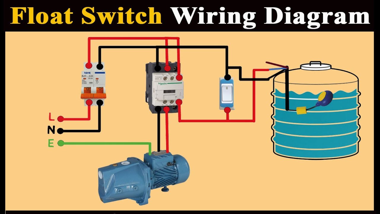
Float level switch wiring diagramConnection diagram of the level control system Reservoir circuit – basic motor control.
.


(a) Electric panel with switches and LEDs of the level control system
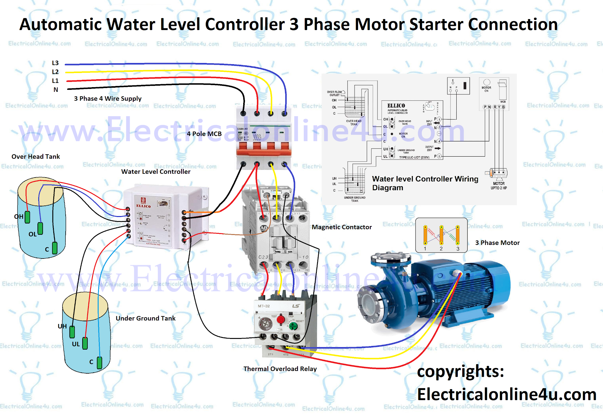
Automatic Water Level Controller Wiring Diagram For 3 phase
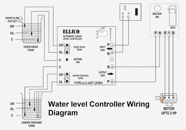
Automatic Water Level Controller Wiring Diagram

Level Up Control Panel is Dead - Grand Design Owners Forums

PI&D for the level control loop with the MPS PA compact workstation

Instrumentation and Process Control
3 float septic system wiring diagram - FiezaFynnley
